
Best seller, best quality batteries


Professional technical product description
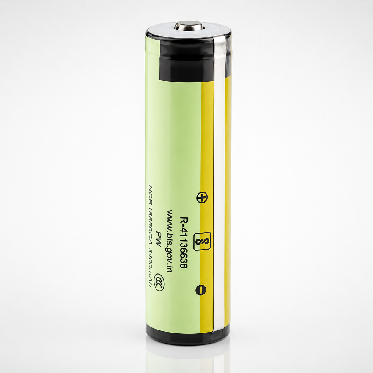
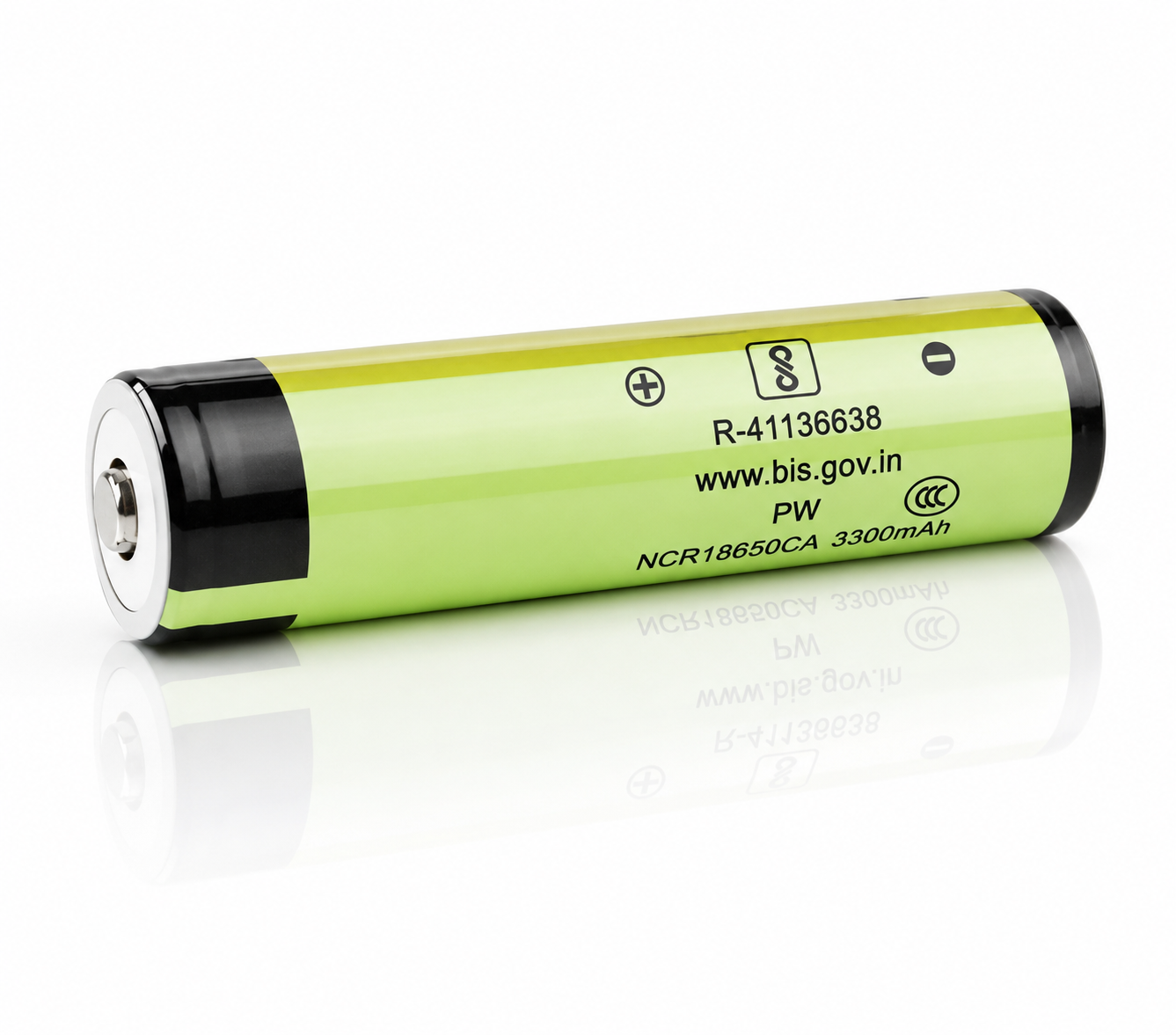
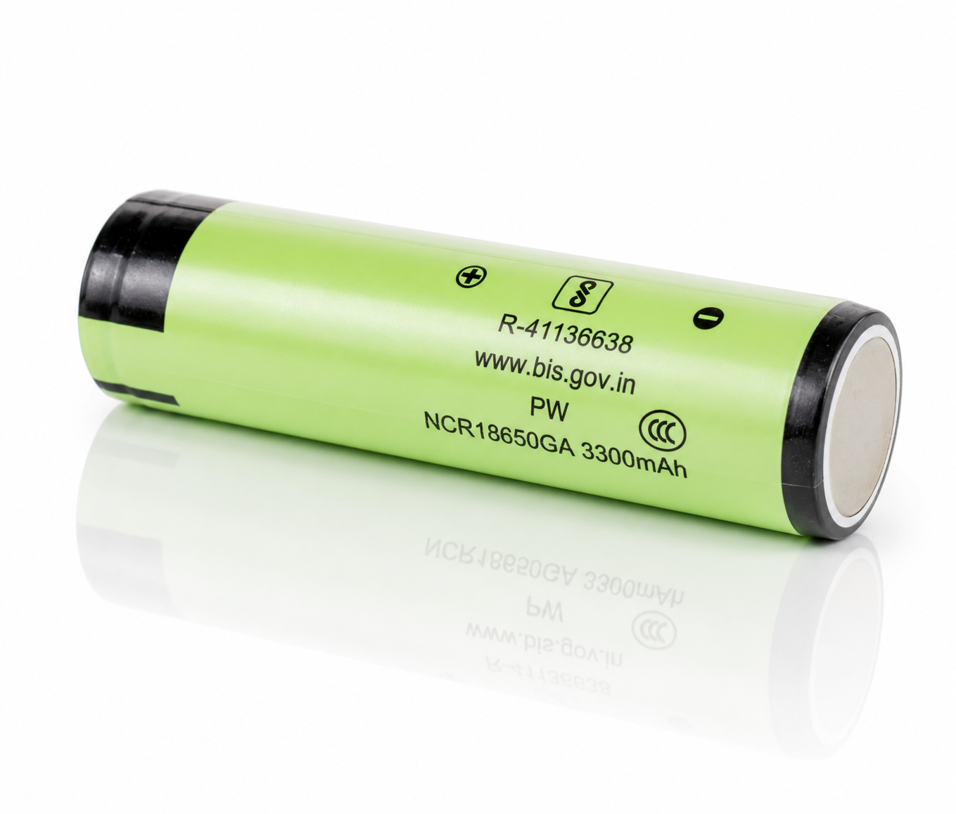
Panasonic NCR18650GA
Panasonic NCR18650GA
Protected Button Top
High-capacity protected button-top 18650 lithium-ion battery designed for devices that require extended runtime, a raised positive terminal, and onboard protection circuitry. This Shopify-ready technical layout separates the Panasonic/Sanyo NCR18650GA cell core from the protected-button-top assembly, making compatibility, current limits, voltage window, and fitment easier for customers to evaluate.
3450mAh Typical Cell Capacity Protected Button Top Approx. 18.5 × 69.5mm 3.6V Nominal 10A Cell Core / PCB-Limited Use
3450mAhTypical Cell Capacity
3350mAhMinimum Cell Capacity
3.6VNominal Voltage
4.2VMax Charge Voltage
10ACell-Core Max Discharge
≈69.5mmProtected Button-Top Length
Panasonic NCR18650GA Protected Button Top 3450mAh Battery
This protected version of the Panasonic NCR18650GA is built for devices that require a longer button-top 18650 cell with integrated protection. The underlying NCR18650GA chemistry is energy focused, offering high capacity and strong runtime per cell, while the button-top and PCB assembly improve compatibility with flashlights, electronics, and other devices designed specifically for protected cells.
For technical accuracy, the page distinguishes between the bare cell specification and the protected button-top assembly. The cell core is specified up to 10A continuous discharge, but the product listing notes that the PCB may limit real-world applications to about 6A. Device compatibility should therefore be based on both physical length and current draw.
Compatibility note: this cell is longer than a standard flat-top unprotected 18650. Do not assume it will fit every device labeled “18650.” It is intended for devices that explicitly accept protected button-top cells around 69.5mm long.
| Brand / Model | Panasonic / NCR18650GA |
|---|---|
| Assembly Type | Protected button-top 18650 lithium-ion battery |
| Top Style | Button top |
| Protection | Yes — PCB protection circuit |
| Nominal / Typical Capacity | 3450mAh cell-core typical capacity at 4.20V charge |
| Minimum Capacity | 3350mAh cell-core minimum capacity at 4.20V charge |
| Rated Capacity | 3300mAh cell-core rated capacity at 4.20V charge |
| Nominal Voltage | 3.6V |
| Maximum Charge Voltage | 4.20V ±0.03V |
| Reduced Charge Voltage Option | 4.15V ±0.03V for life-end / cycle-life control strategies |
| Discharge Cut-Off Voltage | 2.50V per cell |
| Standard Charge Current | 1.675A or less at +10°C to +45°C |
| Low-Temperature Charge Current | 0.838A or less at 0°C to +10°C |
| Continuous Discharge Rating | 10A cell-core maximum PCB may restrict to 6A in many applications |
| Internal Resistance | <38mΩ AC impedance at 1kHz for the cell core |
| Protected Dimensions | Approx. 18.5mm × 69.5mm protected button-top assembly |
| Approximate Weight | 49.4g protected assembly |
| Operating Temperature | Charge: +10°C to +45°C; Discharge: -20°C to +60°C |
| Cell Surface Temperature | Do not exceed 70°C cell surface temperature |
| Rechargeable | Yes |
Electrical operating envelope at a glance.
These quick-reference visuals summarize voltage range, current limits, protection behavior, and capacity-to-energy translation.
1. Protected Current Stack
The cell core and protection circuit must both be considered when matching this battery to a device.
2. Voltage Operating Window
Per-cell voltage limits for charging and discharge cut-off.
3. Capacity and Energy Translation
Approximate nominal watt-hours using typical cell capacity and nominal voltage.
4. C-Rate Conversion
For a 3450mAh cell, 1C equals approximately 3.45A.
| 0.67A | ≈0.19C rated-capacity test current |
|---|---|
| 1.675A | ≈0.49C standard charge current |
| 3.35A | ≈0.97C cycle-life / higher-rate capacity test current |
| 6A | ≈1.74C typical PCB-governed application current reference |
| 10A | ≈2.90C cell-core maximum continuous discharge |
Protected button-top design changes fitment, current behavior, and use case.
The added button top and protection PCB make this battery easier to use in compatible consumer devices, especially lights and electronics that require a raised positive terminal. The tradeoff is added length and a current path through the protection circuit. That means two compatibility checks are required: physical fit and device current draw.
The underlying NCR18650GA cell is specified as a 10A maximum discharge cell, but this protected assembly is best matched to moderate-load devices unless the device manufacturer confirms compatibility with this exact protected format.
Protection-circuit purpose
| Over-charge support | Helps guard against operation above the safe charge region. |
|---|---|
| Over-discharge support | Helps reduce risk from excessive cell depletion. |
| Short-circuit support | Helps interrupt extreme fault-current conditions. |
| Important limitation | Protection does not make the cell misuse-proof; physical damage, heat, wrong chargers, and incompatible devices can still create hazards. |
5. Protection Circuit Flow Diagram
Simplified current path through a protected button-top 18650 assembly.
6. Protected vs. Flat-Top Fitment
Typical fit difference between the unprotected flat-top cell and this protected button-top assembly.
High-runtime discharge behavior favors moderate-load devices.
The NCR18650GA is an energy-focused 18650. It delivers excellent capacity, but high current increases voltage sag, heat, and stress. The simplified graph below visualizes voltage versus capacity for light, moderate, and high-load operation.
7. Simplified Discharge-Curve Graph
Voltage vs. capacity illustration for 0.67A, 3.35A, and 10A discharge. Simplified for product-page visualization.
8. Estimated IR Voltage Drop
Using the cell-core <38mΩ AC impedance specification as a rough planning reference. The PCB adds additional path resistance.
Charge strategy and temperature management affect runtime, safety, and cycle life.
The NCR18650GA specification includes both 4.20V and 4.15V charge options. Lower charge voltage reduces usable capacity but can improve cycle characteristics in products designed for long service life.
9. Charge Profile Reference
Standard charge is CC/CV at 1.675A to 4.20V, with a 4-hour standard charge time.
10. 4.20V vs. 4.15V Capacity Trade-Off
Reduced charge voltage lowers capacity but can support longer-life design strategies.
11. Thermal Operating Envelope
Published cell-core operating range and maximum surface temperature limit.
12. Cycle-Life Visualization
After 300 cycles at 3.35A discharge, the specification uses discharge-time criteria at both 4.20V and 4.15V charge settings.
Mechanical fitment is the main difference from the flat-top NCR18650GA.
The protected button-top assembly is significantly longer than a standard unprotected 18650. Confirm both length and positive-terminal style before purchase.
13. Protected Button-Top Dimension Diagram
Protected assembly approximate envelope for device compatibility checks.
14. Single-Cell Device Design Formulas
Protected cells are most commonly used individually in compatible devices.
Nominal Energy ≈ 3.45Ah × 3.6V = 12.4Wh
Full Charge Voltage = 4.20V
Discharge Cut-Off = 2.50V
Check Device Current ≤ PCB / Device Limit
15. Series / Parallel Use Guidance
Informational only. Protected single cells are usually not the best choice for custom multi-cell packs.
| Single-cell devices | Best fit for compatible protected button-top lights and electronics. |
|---|---|
| Series packs | Use caution because individual PCBs can trip unevenly. |
| Parallel packs | Use caution because current sharing and PCB trip behavior can vary. |
| Professional packs | Use matched unprotected cells with a purpose-built pack-level BMS unless the design specifically requires protected cells. |
16. Common Voltage Examples
Per-cell voltage references for device electronics and chargers.
| Storage / shipment | Partial state of charge is preferred for storage and shipping. |
|---|---|
| Nominal | 3.6V per cell |
| Full charge | 4.20V per cell |
| Reduced charge option | 4.15V per cell for life-oriented charging strategies |
| Discharge cut-off | 2.50V per cell |
Use the protected NCR18650GA only in compatible, correctly specified devices.
A protection circuit improves safety margins, but it does not override the need for correct charging, physical fit, temperature limits, and device-current compatibility.
17. Suggested Control Threshold Map
System-level guidance for chargers and electronics using protected NCR18650GA cells.
| Charge upper limit | 4.20V per cell; 4.15V option for life-oriented designs |
|---|---|
| Discharge floor | 2.50V per cell |
| Charge current | 1.675A or less in normal charge range; 0.838A or less in low-temperature charge band |
| Temperature gate | Charge +10°C to +45°C; discharge -20°C to +60°C |
| Surface temperature | Do not exceed 70°C cell surface temperature |
| Device current | Confirm draw is below the PCB/device limit; many applications should treat 6A as a practical PCB-governed reference. |
18. Risk-Control Checklist
Recommended use practices.
- Use only in devices that specifically accept protected button-top 18650 cells.
- Do not force the cell into tight battery compartments.
- Use only lithium-ion chargers rated for 4.20V cells and compatible with button-top protected batteries.
- Do not rely on the protection PCB as a substitute for proper device design.
- Never carry loose cells with conductive objects such as keys, coins, tools, or metal cases.
- Do not use if the wrap, button top, protection PCB end, or insulator ring is damaged.
- Keep away from water, fire, excessive heat, children, and unapproved applications.
- Do not disassemble, puncture, crush, modify, incinerate, solder, or weld directly to this finished protected cell.
Best suited for protected-cell devices where runtime matters.
High-Output Flashlights
- Strong fit for lights requiring protected button-top 18650 cells.
- High capacity supports extended runtime at moderate output levels.
Portable Electronics
- Good for devices designed around protected 69mm-class 18650 batteries.
- Confirm spring length, button-top requirement, and current draw.
Medical / Instrumentation
- Useful where compatible equipment requires a protected cell format.
- Confirm regulatory and device-manufacturer battery requirements before use.
Runtime-Focused Devices
- Excellent option when capacity matters more than extreme current output.
- Best for moderate-current loads that stay within PCB and device limits.
Chargers / Holders
- Use only chargers and holders that accept longer protected button-top cells.
- Flat-top-only chargers or short battery tubes may not fit this cell.
Custom Packs
- Usually not the preferred choice for multi-cell custom packs.
- Use matched bare cells and a pack-level BMS for most professional assemblies.
19. Selection Bias: Safety Format vs. Maximum Current
for shoppers choosing between protected runtime cells and high-drain unprotected cells.
20. Application Suitability Matrix
Simple product-page fit guidance.
| Protected-button flashlight | Strong fit |
|---|---|
| Runtime-focused electronics | Strong fit |
| Flat-top-only devices | Not compatible |
| High-current tools | Use high-drain cells instead |
| Multi-cell custom packs | Use pack-level BMS designs |
| Vape / e-cigarette devices | Do not use |
Safety, Handling & Compatibility Notice
This product is a protected lithium-ion battery, but it still requires correct handling, charging, storage, and device compatibility. The protection circuit is a safety layer, not a guarantee against misuse. Improper handling can lead to overheating, venting, fire, or explosion.
- Use only in devices compatible with protected button-top 18650 cells around 69.5mm long.
- Charge only with lithium-ion chargers designed for 4.20V 18650 cells.
- Never short circuit, crush, puncture, incinerate, disassemble, or expose the battery to water.
- Do not use cells with damaged wraps, dented cans, damaged buttons, or exposed PCB components.
- Do not mix with cells of different age, capacity, model, state of charge, or protection behavior.
- Do not solder or weld to the finished protected battery.
- Store and transport in non-conductive cases; never carry loose cells in pockets or bags.
- Not for e-cigarette, vape, or similar use.
Final device compatibility and safety remain the responsibility of the integrator or end user.
Common technical questions about the Panasonic NCR18650GA Protected Button Top.
What is the capacity of this battery?
The underlying NCR18650GA cell has a typical capacity of 3450mAh, a minimum capacity of 3350mAh, and a rated capacity of 3300mAh when charged to 4.20V under the published cell specification.
Is this the same as the flat-top NCR18650GA?
No. It uses the same NCR18650GA cell family, but this version adds a button top and protection PCB, making it longer and intended for devices that require protected button-top cells.
How long is the protected button-top version?
The product listing gives approximate protected dimensions of 18.5mm × 69.5mm. That is longer than a standard unprotected 18650 and may not fit all devices.
What is the discharge rating?
The NCR18650GA cell core is specified up to 10A maximum continuous discharge. The product listing notes that the PCB may restrict many applications to about 6A, so device current draw should be checked before use.
What does “protected” mean?
Protected means the finished battery includes a PCB designed to help guard against certain electrical faults such as over-charge, over-discharge, and short-circuit conditions. It does not protect against all forms of misuse or physical damage.
What charger should be used?
Use a charger designed for 4.20V lithium-ion 18650 batteries and compatible with longer protected button-top cells. Do not use chargers that force the cell, damage the wrap, or use the wrong voltage profile.
What is the correct discharge cut-off voltage?
The cell specification lists a 2.50V discharge end voltage. The protection PCB or host device may disconnect the cell before that point depending on design.
Can I use this in a flashlight?
Yes, if the flashlight is designed for protected button-top 18650 batteries of approximately this length and if the light’s current draw is within the protected battery’s operating range.
Can I use this in a flat-top-only device?
No. A protected button-top cell is longer and has a raised positive terminal. Flat-top-only devices may not fit, may not close properly, or may apply excessive pressure to the battery.
Can this battery be used in custom battery packs?
It is not usually the preferred choice for custom multi-cell packs because each cell has its own protection PCB that may trip unevenly. Professional packs generally use matched unprotected cells with a pack-level BMS.
What temperature range is allowed?
The cell specification lists +10°C to +45°C for charging and -20°C to +60°C for discharging. The cell surface temperature should not exceed 70°C.
What is the benefit of 4.15V charging?
Charging to 4.15V reduces usable capacity compared with 4.20V, but the specification discusses reduced-voltage charging as a strategy that can improve safety and cycle characteristics in long-life designs.
Can I carry this battery loose?
No. Even protected cells should be transported in a non-conductive battery case. Loose cells can short against keys, coins, tools, or other metal objects.
Customer Reviews
Overall rating: 4.5 / 5 from 50 reviews.
Gave them a quick charge and put them in the flashlights. Time will tell how long they will last.
Awesome batteries great service
Batteries were real colse to the advertised ratting. like you would expect from name brand cells
Shipped quickly and came in perfect condition. Thank you!
Awesome will buy more.
High Quality, Fair Price, Fast Delivery
Wrong size. Expecting AA size, but is much larger.

The batteries are suppose to be 3450mAh but it only charges to 2800mAh. I want my money back or replaced with the correct ones.
Exactly what I wanted and needed. Love this store
I couldn’t get them to work in my flashlights
Got what I wanted, it worked and arrived on time.
Great battery
Fast shipping, and the battery arrived in perfect condition. It fits properly and works exactly as expected. Very satisfied with the purchase.
purchase arrived as described.

Batteries charged to spec > 3300 mAh and appear to be of high quality. Unfortunately a bit too fat to fit in my flashlight.
👍🏻👍🏻 Exactly what I ordered. 📬 Shipping was F~A~S~T! 📦 Packageed Well. I would Recommend. Although I have only had the battery a few weeks it works well and I would recommend this & the Flat Top version as well if you need.
Great for solar electronics projects, having the protection is a nice peace of mind.
This was a real protected battery. I use these with a flashlight.
as advertised, quick ship
Great battery. A+!
The battery was advertised as 3450mAh, but had 3300mAh written on the casing, and when measured turned out to be only 3160mAh, 8.4% less. But the main problem was the battery length was 3-4 mm too long so it will not fit my cordless soldering iron, the reason I bought it. It is no use to me as it is. I wrote an email to the 18650 store, but never heard back. Not a happy customer!!
Fits my uConsole perfectly! Fast shipping.
All good here.
Jjj
Great seller with excellent information about each product. Highly recommended.
Arrived on time and it was packaged well. Would buy this again in the future to be honest
Best 18650 by far, great performance, long lasting
Very fast and accurate.
I did my research online, and this was the place to buy these batteries. They weigh substantially more than the cheap ones they replaced, and they work great.
Exactly as described. Perfect fit for my uvBeast V3 365nm UV Flashlight.
I love the batteries and the service. My only criticism (but it may be a function of all protected batteries) is that they were a muther bear to force into my battery holder...
I ordered these batteries twice within a week -- after realizing I had miscounted what we needed. We now have 7 new batteries and a battery charger. I charged all of them and they are ready for use. I look forward to using these for a number of years.
Great replacement for my solar powered security light with 25% higher capacity. Perfect fit and improved performance. Very pleased.
The battery was shipped promptly. It was advertised as a Panasonic, but there is no branding on the battery at all. It weighs about the same as other batteries that I have of this capacity and model.
These batteries seem to do the job.
Easy efficient shopping, lightning fast delivery, i recently had a bad experience with another battery seller, so this is a very welcome change. The batteries came at least partially charged, buy had no info on their relative condition, they took quite awhile on my charger to get to full charge, so it would be nice if some notes on condition @ sale & optimized charging conditions (charger rating/voltage) were included. As a customer I’ll definitely be back to your site!
It's great to find a source for high quality cells. I'll definitely be buying more from y'all.
Does what it should.
Nice battery