

Awesome batteries, stable and long lasting
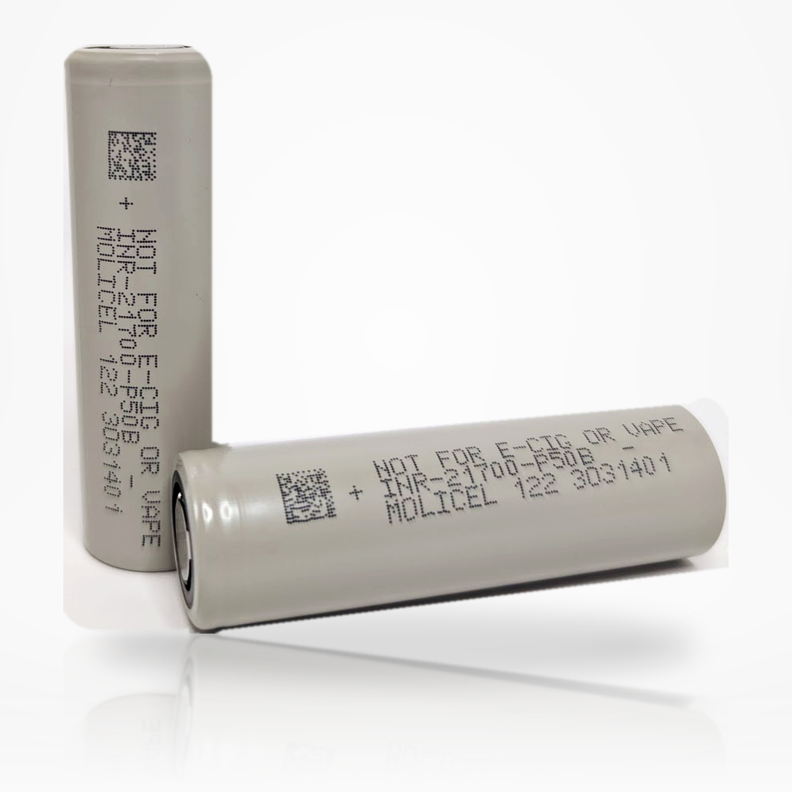
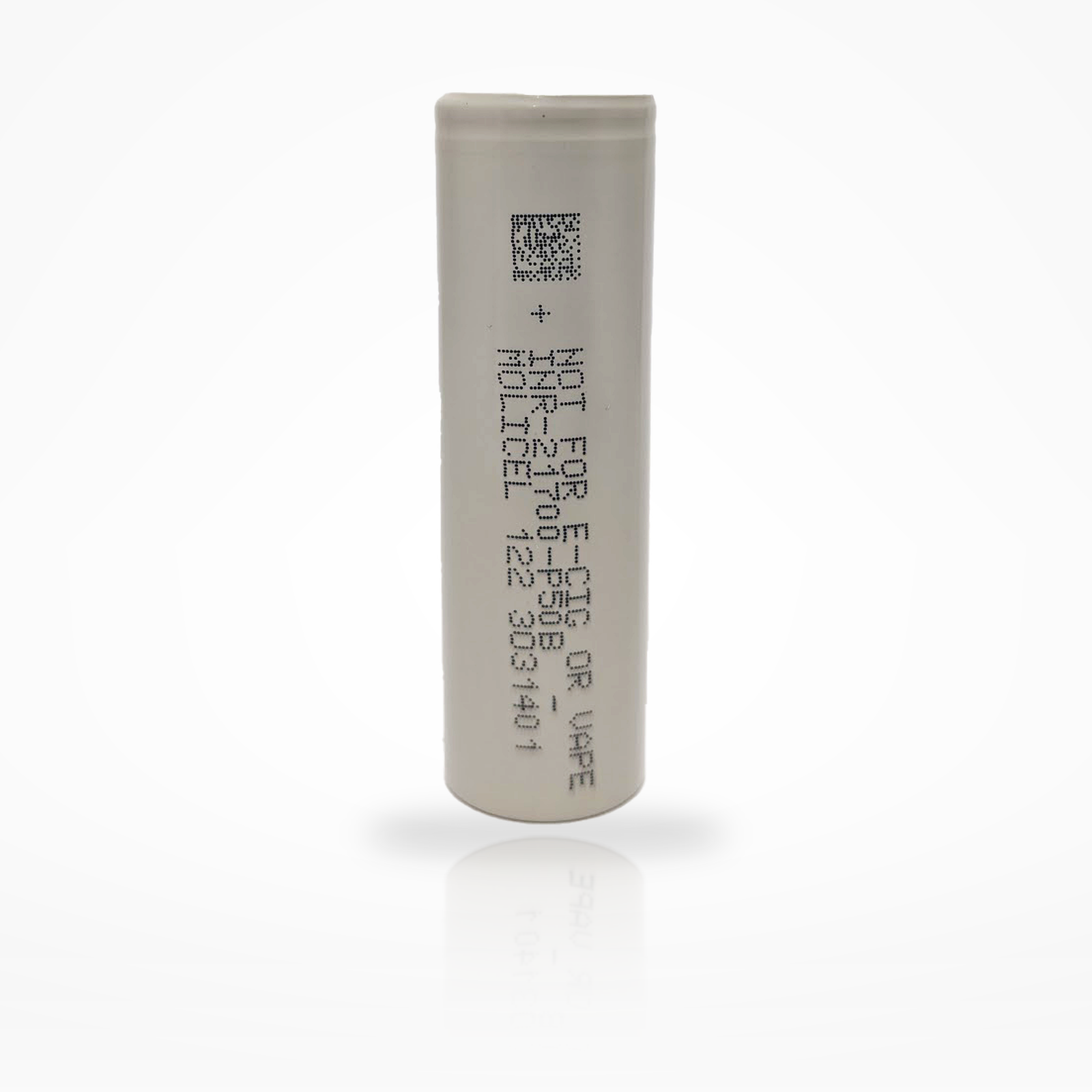


Market-leading 5.0Ah 21700 ultra-high-power lithium-ion cell engineered for applications that demand both high discharge current and high energy density.
The Molicel P50B is a next-generation 21700 power cell built for demanding designs where high current, runtime, and energy density must all be optimized together. Compared with earlier high-power 21700 cells, the P50B increases capacity to 5.0Ah while maintaining a 60A discharge-current class and very low impedance.
For professional product-page accuracy, the P50B should be presented as a 60A cell with an 80°C discharge-current cut-off condition and a 25A maximum charge current with a 70°C cut-off condition. It is an ultra-high-power bare cell and should be engineered into a protected, temperature-monitored battery system.
| Brand / Model | Molicel INR-21700-P50B |
|---|---|
| Cell Series | Molicel ultra-high-power cell |
| Cell Type | 21700 cylindrical lithium-ion rechargeable cell |
| Typical Capacity | 5000mAh / 18.0Wh |
| Minimum Capacity | 4850mAh / 17.5Wh |
| Nominal Voltage | 3.6V |
| Charge Voltage | 4.20V |
| Discharge Cut-Off Voltage | 2.50V |
| Standard Charge Current | 5.0A |
| Maximum Charge Current | 25A with 70°C cut-off Thermal control required |
| Standard Charge Time | 1.5 hours |
| Continuous Discharge Current | 60A with 80°C cut-off |
| Typical Impedance | 6.5mΩ AC at 30% SOC; 12.8mΩ DC at 50% SOC |
| Ambient Charge Temperature | -20°C to 60°C |
| Ambient Discharge Temperature | -40°C to 60°C |
| Energy Density | 714Wh/L volumetric; 260Wh/kg in the data sheet, with product page marketing also using 265Wh/kg |
| Dimensions | 21.55mm max diameter × 70.15mm max height |
| Weight | 71g max |
| Protection | No — unprotected flat-top cell |
These quick-reference visuals summarize the P50B’s current capability, voltage window, energy translation, and C-rate interpretation.
Key current reference points for standard charge, maximum charge, discharge-rate curves, and continuous discharge rating.
Basic per-cell voltage limits used for charger, BMS, and pack design.
The data sheet lists 18.0Wh typical energy.
For a 5000mAh cell, 1C equals approximately 5A.
| 1.0A | ≈0.2C low-rate reference |
|---|---|
| 2.5A | ≈0.5C reference |
| 5A | 1C standard charge reference |
| 25A | 5C maximum charge current |
| 50A | 10C high-rate discharge reference |
| 60A | 12C continuous discharge rating with 80°C cut-off |
The P50B data sheet shows discharge-rate curves across low-current and high-current conditions, including 50A and 60A. The cell is rated for 60A continuous discharge, but that rating is tied to an 80°C cut-off condition, so real pack performance depends on cooling, interconnect resistance, BMS sizing, cell spacing, and load profile.
The simplified discharge-curve graph below visualizes voltage versus delivered capacity under light, medium, high, and maximum-current conditions. It is not a digitized manufacturer graph; it is a product-page visualization designed to show how increasing load increases voltage sag and can reduce usable capacity under cutoff-limited conditions.
| 0.2C / 0.5C / 1C | Low-rate and normalized data-sheet curve references |
|---|---|
| 10A / 20A / 30A | Medium-to-high-load discharge curve references |
| 50A | Very-high-load data-sheet curve reference |
| 60A | Continuous discharge rating with 80°C cut-off |
| Design takeaway | For high-current packs, validate voltage sag and cell temperature under the actual enclosure, BMS, weld, and busbar design. |
Voltage vs. capacity illustration for 5A, 30A, 50A, and 60A operation. Simplified for product-page visualization.
Planning reference using Molicel’s typical AC and DC impedance values. Real pack sag includes cells plus interconnects.
Molicel’s P50B data sheet includes charge curves, discharge-rate curves, discharge-temperature curves, and cycle-characteristics curves. These are condensed into customer-friendly diagrams below.
Standard charge: 5A to 4.2V with 1.5-hour standard charge time. The data sheet also charts 25A maximum charge behavior.
Published ambient charge and discharge temperature ranges.
Customer-friendly summary of the P50B discharge-rate curve family.
The data sheet charts discharge behavior from -40°C through 60°C.
Data-sheet cycle curves include +1C/-1C, +3C/-1C, +5C/-1C, and constant-power discharge families.
Data-sheet and product-page energy density values for design comparison.
| Typical Energy | 18.0Wh |
|---|---|
| Minimum Energy | 17.5Wh |
| Volumetric Energy Density | 714Wh/L |
| Gravimetric Energy Density | 260Wh/kg in data sheet; product page also markets 265Wh/kg |
| Design implication | Very high energy for an ultra-high-power 21700, with strong power-to-energy ratio and low impedance. |
The live listing uses rounded dimensions, while Molicel’s data sheet provides maximum envelope values. Use the maximum values for fixture clearance, holder selection, and pack CAD.
Mechanical envelope based on Molicel maximum dimensions.
Quick math for series/parallel planning. Validate current limits thermally and electrically.
Pack Voltage ≈ Series Count × 3.6V
Pack Capacity ≈ Parallel Count × 5.0Ah
Pack Energy ≈ S × P × 18.0Wh
Cell-Level Current Capability ≈ Parallel Count × 60A
Approximate scaling using cell-level continuous discharge rating, not a finished-pack guarantee.
| 1P | 5.0Ah, 18.0Wh, 60A cell-level current reference |
|---|---|
| 2P | 10.0Ah, 36.0Wh, 120A cell-level current reference |
| 3P | 15.0Ah, 54.0Wh, 180A cell-level current reference |
| 4P | 20.0Ah, 72.0Wh, 240A cell-level current reference |
| 5P | 25.0Ah, 90.0Wh, 300A cell-level current reference |
Nominal voltage examples only. Full-charge and cut-off pack voltages scale separately.
| 1S | 3.6V nominal / 4.2V full / 2.5V cut-off |
|---|---|
| 3S | 10.8V nominal / 12.6V full / 7.5V cut-off |
| 4S | 14.4V nominal / 16.8V full / 10.0V cut-off |
| 5S | 18.0V nominal / 21.0V full / 12.5V cut-off |
| 10S | 36.0V nominal / 42.0V full / 25.0V cut-off |
| 13S | 46.8V nominal / 54.6V full / 32.5V cut-off |
This is an unprotected ultra-high-power cell. Safe implementation requires a charger, BMS, fuse strategy, interconnect design, and thermal-management plan that respect the cell’s limits.
System-level control guidance derived from the live listing and Molicel data-sheet values.
| Charge upper limit | 4.20V per cell |
|---|---|
| Discharge floor | 2.50V per cell |
| Ambient charge range | -20°C to 60°C |
| Ambient discharge range | -40°C to 60°C |
| Standard charge | 5A CC-CV to 4.2V, 1.5-hour standard charge reference |
| Maximum charge | 25A with 70°C cut-off; validate thermally before use |
| Continuous discharge | 60A with 80°C cut-off, subject to system-level thermal and interconnect validation |
Recommended pack-building and use practices.
Product-page positioning for shoppers comparing high-power and high-energy cells.
Simple product-page fit guidance.
| Hyper EV / racing | Strong fit with validation |
|---|---|
| Drones / eVTOL | Strong fit |
| E-motorcycle / mobility packs | Strong fit with BMS and thermal design |
| Backup battery units | Strong fit for engineered systems |
| Maximum runtime only | Compare against energy-focused cells |
| Unmanaged consumer devices | Not recommended |
This product is an unprotected lithium-ion cell. It should only be used by customers who understand lithium-ion cell safety and who are using the battery in compatible hardware, managed packs, or professionally designed assemblies. Improper use can lead to overheating, venting, fire, or explosion.
The P50B has a typical capacity of 5000mAh and a minimum capacity of 4850mAh. The data sheet lists typical energy as 18.0Wh and minimum energy as 17.5Wh.
The current live product title and Molicel data identify the P50B as a 60A cell. The 60A continuous discharge rating uses an 80°C cut-off condition, so pack design must include proper thermal control.
No. This is an unprotected flat-top 21700 cell and should be used only in equipment or packs with appropriate electrical and thermal protection.
Use a lithium-ion charger or battery-management system that uses a CC-CV profile to 4.20V per cell. The standard charge current listed by Molicel is 5A.
Yes. The data sheet lists a 25A maximum charge current with a 70°C cut-off condition, and Molicel describes the cell as supporting a 5C fast charge rate. High-current charging should be used only with temperature sensing and validated pack-level controls.
The data sheet states a 2.50V discharge cut-off voltage per cell. Many pack designers choose a higher system cut-off to reduce stress and improve service life.
Yes. It is intended for high-power battery pack applications when cell matching, spot welding, BMS sizing, fusing, insulation, current sharing, and thermal validation are properly engineered.
Direct soldering is not recommended. Spot welding is the preferred pack-assembly method because it reduces the risk of heat damage to the cell.
Molicel lists the maximum cell envelope as 21.55mm diameter and 70.15mm height, with a maximum weight of 71g. Always confirm physical fit in the actual device or holder.
The P50B data sheet lists -20°C to 60°C for ambient charging and -40°C to 60°C for ambient discharging. High-current use should include temperature monitoring and derating.
It is designed for both high power and high energy. It offers a 5.0Ah capacity while retaining a 60A discharge-current class, making it suitable for premium designs where power-to-energy ratio is critical.
It indicates very low cell impedance at 30% SOC, which helps support high-current delivery and lower voltage sag. Real pack resistance also includes welds, nickel, busbars, wiring, holders, fuses, and BMS components.
The live listing uses a general 1000+ cycle-life statement, and Molicel’s product page highlights improved cycle life under +1C charge / -100W discharge conditions. Actual cycle life depends on temperature, charge current, discharge power, depth of discharge, and pack design.
No. Loose transport is unsafe because conductive objects can short the terminals. Always use a non-conductive battery case.
Overall rating: 4.9 / 5 from 78 reviews.
Awesome batteries, stable and long lasting
Awesome store
Absolutely the best batteries!

These fixed a device with bad batteries. They work perfectly and are great quality that I expect from this site.
Great battery's at a great price. Can't complain.. decent shipping also...
Fast shipping, exactly as specified
Now just waiting on HackerGadgets to ship the battery board….
Fast shipping great batteries
A very high-quality product. I recommend everyone to buy from this store! Thank you for the excellent service!
I always get my batteries from 18650BatteryStore.com and have been for years. The battery are always the real deal. Shipping is great!!! Thank you!!!
Good batteries
Fast shipping, exactly as described, perfect!
Great price and fast shipping

Definitely has some competition from the tabless cell market but the molicel is always considered the gold standard.
I bought the molicel p50b 21700 batteries for a handheld device and they work perfectly. This is a trusted company with legit batteries. I would definitely recommend doing business with them.
Excellent battery cells with great capacity and performance!

Consistency with a track record is hard to ignore,

They are the racers edge in the PEV world
Perfect fit and function in my yllvape 3.0 induction heater.
Works great AND arrived early. Amazing.
The P50B is quite the cell.. it handles whatever you throw at it and barely gets warm (blood temp).. these batteries are truly a testament of how far Molicel pushes the envelope of energy storage. The capacity is very accurate too, ..and with 5C charging, I can see why these don’t stay in stock for very long.. I cannot wait until the P60C makes it’s debut, until then I’m very please with this cell.. The 18650 battery store is one of the few OG shops you can depend on 100%.. I’ve been doing business with these guys for a very, very long time.. They are dependable, have genuine batteries and ship quickly…
Great service. I purchased from this store multiple times and never had any issues. Thank you guys!
quality store, fast shipping. my store of choice
P50B, best batteries on the market bar none
This is a great battery along with excellent shipping! Great experince...
Nice
Nice
This is a potent battery. They sell this like hotcakes, grab them while they're in stock.

Experience the raw power of the leading performance cell!
Works like OEM batteries but much cheaper!
Good
Exactly as ordered and on time.

Only the pros know how this cell gives you the power needed to have the competitive edge!
Outstanding service. Tracking all the way to my door with UPS/18650 Battery. 100% first class batteries . Every one I received had the exact same voltage , that is impressive. Charging to capacity was spot on . The shipping charge is the only downside, but trust me it's worth it if you demand top quality batteries and at a good price.
Everything arrived on time and was as described in product information. Exactly what i needed and the new Molicel P50b cells absolutely DO NOT disappoint. Long lmao bf and the amp limit is insane. Super pleased with my purchase. Will be ordering more from 18650batterystore.com. thanks.

Grade A as always!! Can't wait for the p60b drop 😉

Worked great for what needed. Only brand battery I buy.
Great battery and service
Best of the best 21700 before you get into the tabless construction realm. I have over a dozen of these; all are at or below 19 mOhms, and all charge to just over the claimed 5000 mAh capacity. Haven't got a good way to test discharge current, but they hold up well in single cell, high intensity flashlights.
So far so good!